
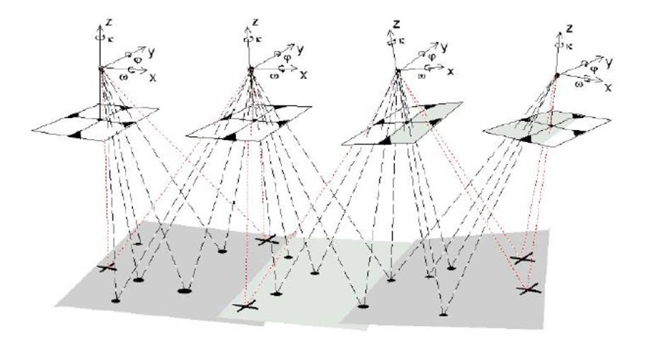
A tie point in aerotraingulation in 3d aerial photogrammetry is a point whose ground coordinates are not known, but is visually recognizable in the overlap area between two or more images. The corresponding image positions of tie points appearing on the overlap areas of multiple images is identified and measured.
 Ground coordinates for tie points are computed during block triangulation.
Tie points can be measured both manually and automatically.
Tie points in aerotraingulation in 3d aerial photogrammetry should be visually defined in all images. Ideally, they should show good contrast in two directions, like the corner of a building or a road intersection.
Tie points aerotraingulation in 3d aerial photogrammetry should also be distributed over the area of the block. Typically, nine tie points in each image are adequate for block triangulation.
The Absolute orientation of a model is a 3D similarity transformation between model space and ground space using ground control points.
Model absolute orientation with respect to the ground requires the determination of six parameters, typically chosen as three shifts(x, y, z), three rotations (omega, phi ,kappa), and one Image id.
To fulfill the number of unknowns in the absolute orientation process, at least three control points are required.
For scaling and leveling of images the client has provided us the no. of GCP points of that area with readings.
In the whole process we have to take care of RMS error while marking tie and pass points in photographs that should be below some value provided by client.
The Root Mean Square (RMS) error in aerotraingulation in 3d aerial photogrammetry represents the difference between the original control points and the new control point locations calculated by the transformation process. The transformation scale indicates how much the map being digitized will be scaled to match the Real world coordinates.


